Introduction
When selecting steel grating for industrial flooring, walkways, platforms, or trench covers, understanding load capacity is the single most critical engineering consideration. A grating load capacity chart is the essential reference tool that engineers, contractors, and safety inspectors rely on to match grating specifications with application requirements. Getting the load rating wrong can lead to structural failure, workplace injuries, and costly rework.
This comprehensive guide covers everything you need to know about steel grating load capacity — from ANSI/NAAMM and DIN load rating standards to deflection criteria, load table interpretation, and step-by-step calculation methods with real-world examples. Whether you are designing a pedestrian walkway requiring L/200 deflection limits or a heavy-duty industrial platform rated for forklift traffic, this guide will help you select the right grating for the job.
What Is a Grating Load Capacity Chart?
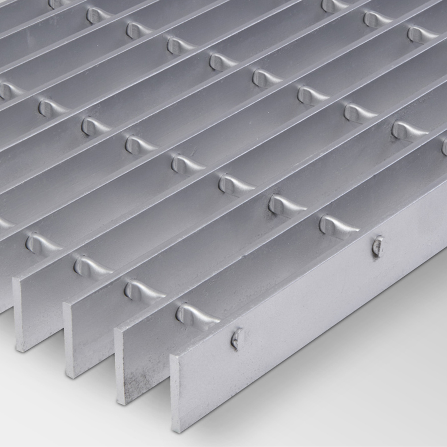
A grating load capacity chart is a tabulated reference that lists the maximum allowable loads for different steel grating configurations. Each chart is typically organized by bearing bar size (depth × thickness), bar spacing, span length, and steel grade. The chart provides both concentrated load ratings (point loads in pounds or kN) and uniform load ratings (distributed loads in psf or kN/m²) for each configuration.
These charts are the industry-standard tool for determining whether a specific grating panel can safely support the expected loads in a given application. They are published by grating manufacturers and industry associations such as the National Association of Architectural Metal Manufacturers (NAAMM) and conform to ANSI standards.
Why Load Capacity Matters
Understanding steel grating load capacity is fundamental to safe and economical design. Underestimating loads can result in grating failure — bent bars, broken welds, or complete collapse — posing serious safety risks to personnel and equipment. Over-engineering, on the other hand, drives up material costs unnecessarily.
The load capacity of steel grating depends on several interacting factors: bearing bar depth and thickness, span length (the distance between supports), bar spacing (typically 30 mm, 40 mm, or 60 mm center-to-center), and the yield strength of the steel used (most commonly A36 mild steel with 250 MPa yield or higher-strength grades). A clear grasp of these parameters and how they appear on a load capacity chart is essential for anyone involved in grating specification.
ANSI / NAAMM Load Rating Standards
In North America, steel grating load ratings are governed by the ANSI/NAAMM MBG 531 standard — "Metal Bar Grating Manual" published by the National Association of Architectural Metal Manufacturers. This standard establishes a uniform system for classifying grating by load-bearing capacity and provides engineers with a reliable basis for specification.
The ANSI/NAAMM system defines load ratings based on the maximum allowable stress method, using a safety factor of 1.5 against the yield strength of the steel. All standard load tables published by NAAMM-compliant manufacturers follow this methodology, ensuring consistency across different suppliers.
NAAMM Loading Classes A through I
The NAAMM MBG 531 standard defines eight loading classes for steel bar grating, designated by letters A through I (excluding some letters). Each class specifies a maximum allowable uniform load and concentrated load for a given span, with a corresponding deflection limit.
| NAAMM Class | Uniform Load (psf) | Concentrated Load (lbs) | Typical Application |
|---|---|---|---|
| A | 75 | 250 | Light pedestrian walkways, catwalks |
| B | 100 | 500 | Pedestrian bridges, light platforms |
| C | 150 | 750 | General walkways, mezzanine floors |
| D | 200 | 1,000 | Light industrial platforms, trench covers |
| E | 300 | 1,500 | Medium industrial platforms, loading areas |
| F | 400 | 2,000 | Heavy industrial platforms, vehicle access |
| G | 500 | 2,500 | Heavy-duty industrial, forklift traffic |
| H | 600 | 3,000 | Extra-heavy duty, truck loading zones |
| I | 750 | 3,500 | Severe service, crane loads |
These load ratings assume the grating is properly supported at both ends, with bearing bars oriented perpendicular to the supports. Each class also defines the maximum allowable deflection, typically set at L/200 or stricter for pedestrian applications.
Concentrated vs Uniform Load Ratings
Steel grating can be subjected to two distinct types of loading, and a proper grating load capacity chart specifies both ratings separately.
Concentrated Load — also called a point load — represents a force applied over a small area, such as a forklift wheel, a machine foot, or a single person standing. It is measured in pounds (lbs) or kilonewtons (kN). Concentrated load capacity is typically the governing factor for grating with shorter spans, where a single wheel load may exceed the uniform load capacity.
Uniform Load — also called a distributed load — represents a weight spread evenly across the entire grating surface, such as stored materials, snow accumulation, or a crowd of people. It is measured in pounds per square foot (psf) or kilonewtons per square meter (kN/m²). Uniform load capacity generally governs for longer spans where the bending moment accumulates across the full surface.
When consulting a load capacity chart, engineers must check both values against the expected loading scenario and select the grating that satisfies the more demanding condition.
DIN / European Load Standards for Steel Grating
In Europe and many international markets, steel grating load capacity is governed by DIN standards, particularly DIN 24537-1 and the European standard EN 10025 for structural steel. The DIN system approaches load classification differently from NAAMM, using a safety factor-based method that ties load ratings directly to material yield strength and geometric section modulus.
Under the DIN system, grating load capacity is calculated using allowable stress design, where the maximum bending stress in the bearing bar must not exceed a specified percentage of the steel’s yield strength (typically 60-65% of the yield stress for static loads). The standard also specifies deflection limits of L/200 for general industrial applications, with stricter limits of L/300 for areas with sensitive equipment.
Key parameters in the DIN system include:
- Bearing bar depth (h) — the vertical dimension of the bar, typically ranging from 20 mm to 75 mm
- Bearing bar thickness (t) — typically 3 mm to 6 mm for standard applications
- Bar spacing (w) — center-to-center spacing, commonly 30 mm, 40 mm, or 60 mm
- Span length (L) — the clear distance between supports in millimeters
- Steel grade — S235JR (235 MPa yield), S275JR (275 MPa), or S355JR (355 MPa)
DIN load charts typically express capacity in kN/m² for uniform loads and kN for concentrated loads, making them directly compatible with European structural design codes (Eurocodes).
Deflection Standards: L/100, L/150, L/200 Explained
Deflection — the amount a grating panel bends under load — is as important as load capacity itself. Even if a grating can support a given weight without permanent deformation, excessive deflection creates an unsafe walking surface, causes discomfort, and can damage equipment mounted on the grating.
Deflection limits are expressed as a fraction of the span length (L). The three most common deflection standards are:
L/200 — The maximum deflection is one two-hundredth of the span length. For a 1,000 mm (1 m) span, the maximum allowable deflection is 5 mm. This is the general-purpose standard for industrial walkways and platforms where moderate deflection is acceptable.
L/150 — A more relaxed standard allowing 1/150 of the span (6.7 mm for a 1 m span). This is sometimes used for heavy-duty industrial areas where absolute rigidity is less critical than load-bearing capacity.
L/100 — The least restrictive standard, allowing 1/100 of the span (10 mm for a 1 m span). This is rarely specified for pedestrian areas but may be acceptable for certain non-traffic applications such as trench covers in low-traffic zones.
The key trade-off is stiffness versus cost. A stiffer grating (L/200 or stricter) requires deeper or thicker bearing bars, which increases material cost. Engineers must balance the deflection requirement against the budget while maintaining safety.
How to Read a Steel Grating Load Table
A grating load capacity chart is typically organized in a row-and-column format with the following structure:
Rows represent different bearing bar configurations. Each row specifies the bar depth (mm), bar thickness (mm), and bar spacing (mm). For example, a row might read “25×5 — 30” meaning 25 mm deep × 5 mm thick bars on 30 mm centers.
Columns represent the span length (distance between supports), usually listed in increments such as 300 mm, 600 mm, 900 mm, 1200 mm, and 1500 mm.
At each row-column intersection, the chart provides two numbers:
- Top number: Uniform load capacity in psf or kN/m²
- Bottom number: Concentrated load capacity in lbs or kN
Most charts also indicate the deflection limit used (L/200, L/150, etc.) at the top of each column, so you can quickly identify which span/bar combinations meet your project’s deflection requirement. Manufacturers typically publish separate charts for each steel grade and for different grating types (welded, press-locked, swage-locked).
When reading a load table, always confirm: (1) the steel grade assumed, (2) the safety factor applied, (3) the deflection criteria, and (4) whether the load values are for concentrated or uniform loading.
How to Calculate Steel Grating Load Capacity
Steel grating load capacity is determined by the section modulus of the bearing bars, the yield strength of the steel, the span length, and the load distribution. This section covers the engineering formula and a practical calculation method that you can apply to any standard grating configuration.
Load Capacity Formula and Step-by-Step Method
The fundamental formula for calculating the load capacity of a single bearing bar is based on the bending stress equation:
σ = M / S
Where:
σ = bending stress (MPa)
M = maximum bending moment (N·mm)
S = elastic section modulus of one bearing bar (mm³)
Step 1: Calculate Section Modulus per Bar
For a rectangular bearing bar: S = (b × h²) / 6
Where b = bar thickness (mm), h = bar depth (mm)
Step 2: Calculate Section Modulus per Meter Width
Distribute the single-bar section modulus across the grating width:
S_per_meter = S × (1000 / bar_spacing)
Where bar_spacing is the center-to-center spacing in mm.
Step 3: Calculate Uniform Load Capacity
For a simply supported beam with uniform distributed load:
w = (8 × σ_allowable × S_per_meter) / (L² × 1000)
Where w = uniform load capacity (kN/m²), L = span length (m), σ_allowable = allowable bending stress (typically 0.6 × yield strength for static loads).
Step 4: Calculate Concentrated Load Capacity
For a point load at mid-span (worst case):
P = (4 × σ_allowable × S_per_meter × span_width) / (L × 1000)
Where P = concentrated load capacity (kN), span_width = the width over which the load distributes (typically 1 m for standard calculations).
Step 5: Check Deflection
Uniform load deflection: δ = (5 × w × L&sup4;) / (384 × E × I)
Where E = modulus of elasticity (200 GPa for steel), I = moment of inertia of the bearing bars per meter width.
For a rectangular bar: I = (b × h³) / 12 per bar, then multiplied by (1000 / bar_spacing) for per-meter-width values.
If calculated deflection exceeds the allowable limit (e.g., L/200), reduce the load or select a deeper/thicker bearing bar.
Load Capacity Calculation Examples
Now let us apply the calculation method to real-world examples. These examples demonstrate how bearing bar size, span length, and steel grade affect the final load rating. All examples use A36 mild steel with 250 MPa yield strength and an allowable stress of 150 MPa (60% of yield).
Example 1: Standard Welded Grating 25×5 mm
Configuration: 25 mm deep × 5 mm thick bearing bars, 30 mm spacing, A36 steel (250 MPa yield), span length = 1,000 mm
Step 1: Section Modulus per Bar
S = (5 × 25²) / 6 = (5 × 625) / 6 = 520.8 mm³
Step 2: Section Modulus per Meter Width
Number of bars per meter = 1000 / 30 = 33.3
S_per_meter = 520.8 × 33.3 = 17,343 mm³/m
Step 3: Moment of Inertia per Bar
I = (5 × 25³) / 12 = (5 × 15,625) / 12 = 6,510 mm&sup4;
I_per_meter = 6,510 × 33.3 = 216,783 mm&sup4;/m
Step 4: Uniform Load Capacity
Allowable stress = 0.6 × 250 MPa = 150 MPa
w = (8 × 150 × 17,343) / (1.0² × 10&sup6;) = 20.8 kN/m²
(Note: 1 kN/m² ≈ 20.9 psf, so this equals approximately 435 psf)
Step 5: Check Deflection at Full Load
δ = (5 × 20.8 × 1000&sup4;) / (384 × 200,000 × 216,783) = 6.25 mm
L/200 = 1000/200 = 5 mm
6.25 mm > 5 mm → Deflection governs!
The actual load must be reduced until deflection meets L/200. Iterating: the maximum load for L/200 compliance is approximately 16.6 kN/m² (347 psf) for this configuration at 1 m span.
Example 2: Heavy Duty Grating 32×5 mm
Configuration: 32 mm deep × 5 mm thick bearing bars, 40 mm spacing, A36 steel (250 MPa yield), span length = 1,200 mm
Step 1: Section Modulus per Bar
S = (5 × 32²) / 6 = (5 × 1,024) / 6 = 853.3 mm³
Step 2: Section Modulus per Meter Width
Number of bars per meter = 1000 / 40 = 25
S_per_meter = 853.3 × 25 = 21,333 mm³/m
Step 3: Moment of Inertia per Bar
I = (5 × 32³) / 12 = (5 × 32,768) / 12 = 13,653 mm&sup4;
I_per_meter = 13,653 × 25 = 341,333 mm&sup4;/m
Step 4: Uniform Load Capacity
Allowable stress = 150 MPa
w = (8 × 150 × 21,333) / (1.2² × 10&sup6;) = 17.8 kN/m² (approximately 372 psf)
Step 5: Check Deflection at Full Load
δ = (5 × 17.8 × 1200&sup4;) / (384 × 200,000 × 341,333) = 7.0 mm
L/200 = 1200/200 = 6 mm
7.0 mm > 6 mm → Deflection governs again.
The deflection-limited uniform load is approximately 15.1 kN/m² (315 psf). For heavy-duty applications requiring forklift traffic, this configuration delivers ample capacity while meeting pedestrian deflection criteria.
These examples illustrate why engineers must always check both stress and deflection when consulting a grating load capacity chart. The governing factor often depends on the specific combination of bar geometry and span length.
Factors Affecting Steel Grating Load Capacity
Several key variables influence the load capacity of steel grating. Understanding these factors helps in selecting the most cost-effective configuration for a given application.
Bearing Bar Depth — This is the most influential geometric parameter. Increasing bar depth from 25 mm to 32 mm increases the section modulus by approximately 64% (since S is proportional to h²). Deeper bars provide significantly higher load capacity and stiffness per unit of material used.
Bearing Bar Thickness — Thicker bars increase the section modulus linearly (S ∝ b). Going from 5 mm to 6 mm thickness provides a 20% increase in capacity, making it a cost-effective upgrade for moderate capacity improvements.
Bar Spacing — Closer bar spacing means more load-carrying bars per meter width. Reducing spacing from 40 mm to 30 mm increases the number of bars by 33%, directly boosting both uniform and concentrated load capacity.
Span Length — Load capacity decreases with the square of the span length for uniform loads (w ∝ 1/L²). Doubling the span reduces capacity to one-quarter, making span length the most critical design parameter.
Steel Grade — Higher-strength steels such as S355JR (355 MPa yield) offer approximately 42% more allowable stress than A36 (250 MPa), translating directly into higher load ratings without changing bar geometry.
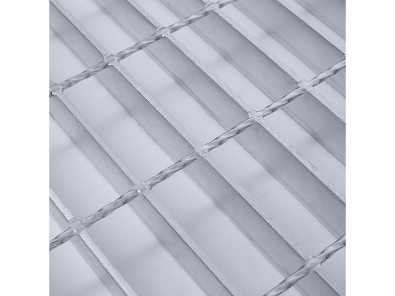
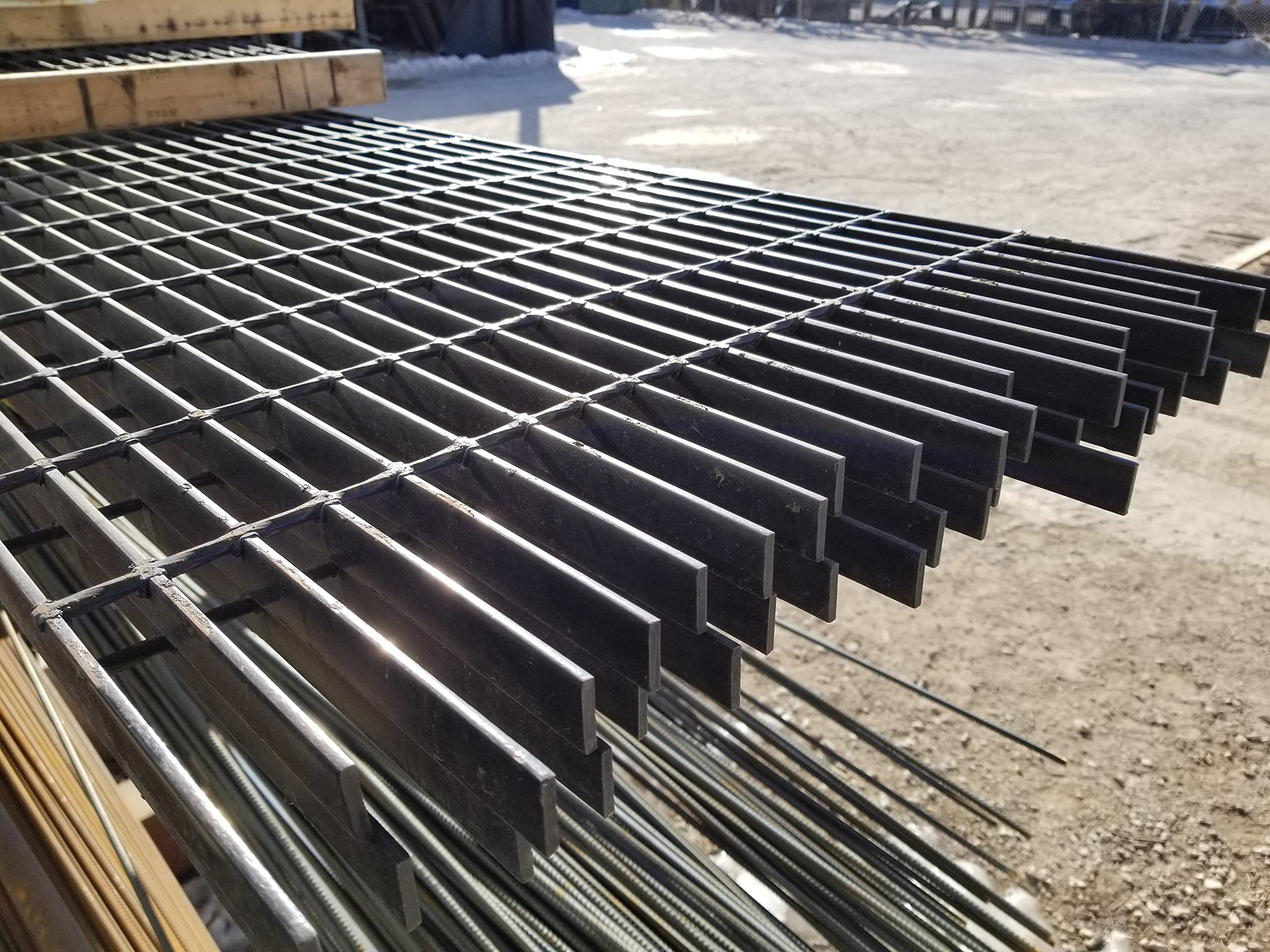
Cross Bar Type and Spacing — Cross bars (the smaller bars perpendicular to bearing bars) contribute minimally to primary load capacity but help distribute concentrated loads across adjacent bearing bars, improving overall panel performance.
Grating Type — Welded grating and press-locked grating have similar load capacities when the same bearing bar sizes are used, though welded connections provide slightly better load distribution. Swage-locked grating may have reduced capacity due to the material removed by the swaging process.
Steel Grating Load Capacity FAQs
What is the load capacity of steel grating?
Steel grating load capacity varies widely based on bearing bar size, spacing, span length, and steel grade. Typical configurations range from 5 kN/m² (104 psf) for lightweight pedestrian grating with 25×3 mm bars at 1.5 m span, to over 50 kN/m² (1,044 psf) for heavy-duty configurations with 50×6 mm bars at 0.6 m span. Always consult a grating load capacity chart from your manufacturer for precise values.
What are the load capacity ratings for industrial floor grating?
Industrial floor grating is typically rated under the NAAMM classification system, ranging from Class A (75 psf uniform) for light pedestrian use to Class I (750 psf uniform) for severe service. Most industrial platforms use Class D through F (200-400 psf uniform).
What are the load ratings for heavy duty steel grating?
Heavy duty steel grating corresponds to NAAMM Classes F through I, with uniform load ratings of 400-750 psf and concentrated load ratings of 2,000-3,500 lbs. These are suitable for forklift traffic, truck loading zones, and heavy machinery platforms.
How much weight can bar grating support?
The weight capacity depends on the specific configuration. A standard 25×5 mm bar grating on 30 mm spacing with 1 m span can support approximately 20 kN/m² (417 psf) uniform load before reaching allowable stress limits, though deflection (L/200) may reduce this to about 16.6 kN/m² (347 psf).
How much weight can welded steel grating support?
Welded steel grating offers the same theoretical load capacity as other types with identical bearing bar geometry. A typical 32×5 mm welded grating at 40 mm spacing with 1.2 m span supports approximately 17.8 kN/m² (372 psf) uniform load, deflection-limited to about 15.1 kN/m² (315 psf) at L/200.
What are the load ratings for different types of grating?
Welded, press-locked, and swage-locked grating types have similar load ratings when the bearing bar dimensions, spacing, and steel grade are the same. The primary difference lies in how cross bars are attached, which affects load distribution and lateral stability rather than the fundamental bending capacity of the bearing bars.
Conclusion
Understanding steel grating load capacity is essential for safe, code-compliant, and cost-effective industrial flooring design. From the NAAMM classification system to the deflection limits of L/100 through L/200, every element of the load rating framework exists to ensure that grating performs reliably under real-world conditions.
A grating load capacity chart is the indispensable tool that translates complex engineering calculations into accessible design data. By learning to read these charts and apply the calculation methods presented in this guide, engineers and specifiers can confidently select the optimal grating configuration for any application — from light pedestrian walkways to heavy-duty industrial platforms supporting forklift and truck traffic.
When in doubt, always consult the manufacturer’s published load tables and verify that the chosen grating meets both the stress and deflection requirements of your specific project. Proper selection based on accurate load capacity data ensures safety, longevity, and cost efficiency for decades of service.